

Introduction to LFGM type pneumatic pulse bag filter
The LFGM type air box pulse bag filter combines the advantages of chamber back blowing and pulse blowing dust removal, overcomes the disadvantages of poor intensity of chamber back blowing dust removal and simultaneous pulse blowing dust removal and filtration, and expands the application range of sub air box pulse bag filters. Due to its unique structure, it greatly improves the dust removal efficiency and extends the service life of the filter bag, making it an excellent bag filter. The LFGM air box pulse bag filter has four series and 33 specifications, with a filtration area ranging from 93m2-4361m2 and a processing air volume ranging from 69003/h-314000m3/h. It is widely used in the building materials, cement, metallurgy, machinery, chemical and refractory materials industries; Dust collection system (or dust removal system) specially used for crushing, drying, coal grinding, powder selection, packaging, warehouse roof, clinker cooling machine, etc. in cement plants; It is also suitable for coal mill dust collection, but anti combustion and explosion-proof measures need to be added, and the structure of the dust collector needs to be correspondingly changed. It can also be applied to dust collection of gases with extremely high dust concentration, such as coal mill systems with O-Sepa powder separators, whose gas dust concentration is as high as 1000g/m3 (standard) or more, and can be used without cyclone dust collectors for pre dust collection. For cold regions in northern China, this dust collector can also be used after adding thermal insulation devices.
Structural characteristics:
This is a bag filter with a segmented structure assembly, which uses a pulse valve on the top of the chamber to alternately clean the filter bags of each chamber with a segmented air stop box pulse cleaning (also known as offline cleaning). It is different from the dust cleaning of a general spray type dust collector. Spray pulse dust cleaning only sprays and cleans each row of filter bags in the same filter chamber, while the other rows of filter bags are still filtered. The cleaning and filtering are carried out simultaneously in one room, and the dust under the cleaning is secondary flown, some of which will be collected by adjacent filter bags, which is not conducive to the filtration of gases with high dust concentration. The LFGM gas box pulse bag filter is operated when the valve is closed in one room to stop filtering. The cleaned dust settles downward in the ash half without secondary flying, which is extremely beneficial for filtering gases with high dust concentration. Moreover, the filter bag in one room can be replaced without stopping the machine.
Dust collectors are divided into four series based on the number of bags: 32 bags/chamber, 64 bags/chamber, 96 bags/chamber, and 128 bags/chamber. Each series is further divided into multiple specifications based on the number of bags, totaling 33 types. Its structure is detailed in the attached selection
The diagram consists of the following parts:
(1) Shell part: including clean room (also known as gas purification box, storage box), filtration room, partition board, maintenance door and shell structure. The cleaning room is equipped with a lift valve and a flower board, and a short spray pipe. The filtering room is equipped with a filter and its framework.
(2) Ash hopper and ash unloading mechanism: There are ash hoppers and screw conveyors, air conveying chutes, and rigid impeller feeders (ash unloading valves) set up according to different series and import dust concentrations.
(3) Inlet and outlet air box body: including inlet and outlet air ducts and middle partition. The single row (or single row) structure is arranged on one side of the shell, and the double row (or double row) structure is arranged in the middle of the shell: the 32 series is smaller without a box, and the inlet and outlet air ducts are respectively connected to the ash hopper and the cleaning room.
(4) Pulse dust cleaning device: including pulse valve, air bag, lifting valve cylinder and its solenoid valve, etc.
(5) Compressed air pipeline and pressure reducing device, oil-water separator, oil mist device, etc.
(6) Pillars, vertical cage ladders, and railings.
Working Principle:
The dusty gas enters from the inlet of the dust collector's inlet and outlet air box (32 series enters from the ash hopper) and then turns to the ash hopper through the inclined partition. At the same time, the airflow speed slows down. Due to inertia, the coarse dust particles in the gas fall into the ash hopper, while the fine dust particles are deflected upwards by the airflow and enter the filtering chamber. The dust adheres to the surface of the filter bag, and the purified gas enters the upper cleaning chamber through the filter bag. It is collected by each cleaning chamber through the outlet and sucked out by the main fan of the dust collection system before being discharged into the atmosphere.
As the filtration process continues, the amount of dust adhering to the surface of the filter bag gradually increases, and the resistance of the airflow passing through also gradually increases. When a certain resistance value is reached (e.g. 1770Pa), it can be manually or through a timed cleaning program with an electronic control instrument, automatically controlling the lifting valve of the Diyi sub chamber that starts the dust collector to close, cutting off the airflow through the filter chamber, and then opening the high-pressure compressed air released by the pulse valve to pulse blow and clean all the filter bags in the Diyi sub chamber air box (stop air cleaning), causing each filter bag to suddenly swell, thereby shaking off the dust accumulated on the bag surface and restoring the pressure difference inside and outside the bag to the starting use state. The dust cannot settle enough to fill the ash hopper, and then the control instrument opens the lifting valve at regular intervals to restore Diyi Filter the chamber, then activate the lift valve of the second chamber, close the filtered airflow of the second chamber, open the solenoid valve of the second chamber to release high-pressure compressed air, stop the air pulse to blow and clean all the filter bags inside the second chamber, remove the dust on the filter bags of the second chamber, and then the control instrument opens the lift valve of the second chamber to restore the filtration of the second chamber. Afterwards, according to the pre specified electrical control program, the filter bags of the third compartment, third compartment, etc. will be stopped and blown to clean the dust until the cleaning of the compartments is completed. The electrical control device will be turned off, and the dust collector will resume formal filtering and dust collection. The time for stopping and blowing the filter bag, the interval between compartments, and the cleaning cycle are controlled by a programmable controller, and all times are adjustable. Please refer to the electrical manual.
Dust collectors generally work under negative pressure, but they can also work under positive pressure without changing their structure.
Main technical performance and selection instructions:
a. The main technical performance data is shown in Table 3-5.
b. Selection instructions:
1. Selection of filtering wind speed:
The filtering wind speed refers to the wind speed (m/min) passing through the filter bag filter material. Some are called air to cloth ratio, which refers to the amount of air passing through a unit area of filter material in m3/min/m2 per unit time, that is, m/min. The selection of filtering wind speed should be based on the characteristics of the filtering medium dust and flue gas, temperature and humidity, dust concentration, cleaning method, and the properties of the selected filter material. The filtering wind speed not only determines the size of the dust collector, but also has a significant impact on the resistance through the filter material, dust collection efficiency, and cleaning effect. To ensure the dust removal effect of the dust collector, improve the service life of the filter bag, and reduce resistance, the filtration wind speed of this dust collector is generally 1.2m/min. For the main dust source points in the cement plant, under the conditions of using this dust collector, it is recommended to use the net filtration wind speed according to Table 1.
The net filtration wind speed refers to the filtration wind speed (m/min) of the original air flow passing through the filtration area of other chambers when one of the chambers of the dust collector is stopped for dust cleaning.
2. Calculation of filtration area:
Follow the steps below for the company to proceed:
AN=Q/60VN,m2
In the formula: AN - net filtration area m2, refers to the sum of the filtration areas of the other chambers when a dust collector stops blowing back in one chamber;
Q - The filtered air volume through the dust collector, also known as the treated gas volume m3/h;
VN - Net filtration wind speed, m/min
3. Selection of operating temperature and filter material
The operating temperature is closely related to the selection of filter media, and the allowable inlet dusty gas temperature varies depending on the filter media. This dust collector generally uses polyester needle punched felt and allows continuous use at temperatures ≤ 120 ℃. When using aramid needle punched felt (Nomex), the upper temperature limit allowed for use is 200 ℃. When using P84 needle punched felt, its allowable temperature is 260 ℃. When the usage temperature of each filter material is exceeded, cooling measures should be taken before the gas enters the dust collector. At the same time, the filter bag can be treated for oil, water, adhesion, and static electricity prevention.
4. Inlet allowable concentration
Due to the special structure of this dust collector, it adopts a stop air pulse blowing cleaning (offline cleaning), so its inlet allowable concentration is higher than traditional pulse blowing cleaning (online cleaning) and other general chamber back blowing dust collectors. The 32 series (small) of this dust collector allows an inlet gas dust concentration of 200g/m3 (standard), while the other 64, 96, and 128 series allow up to 1000g/m3 (standard). The dust concentration at the outlet of the dust collector is ≤ 100mg/m3 (standard).
Technical parameters of LFGM gas box pulse bag filter
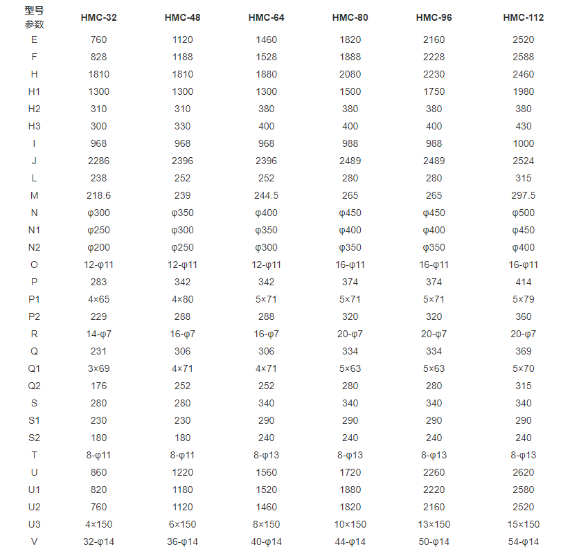
Technical Performance Table of LFGM Gas Box Pulse Bag Dust Collector
Purpose of LFGM type air box pulse bag filter
The information is currently being supplemented. Please stay tuned

 CN
 EN
